Computer Networking
Detailed Computer Networking notes with clear explanations, real-life examples, diagrams, visual illustrations, step-by-step procedures, practical activities and an interactive exam system.
1. Introduction to Computer Networking
Computer networking is the process of connecting two or more computers or digital devices so that they can communicate and share information, services and resources. A network may contain desktop computers, laptops, servers, printers, routers, switches, smartphones and wireless access points.
Without networking, each computer would operate mainly as an isolated system. Networking makes it possible for users to access shared files, communicate with one another, use common printers and connect to online services.
Why Networks Are Important
- Resource sharing: one printer, storage system or internet connection can be used by multiple users.
- Communication: users can exchange messages, files and participate in online meetings.
- Centralized management: administrators can manage shared services and user access more efficiently.
- Information sharing: authorized users can access information stored on networked systems.
Simple Network Diagram
                         INTERNET
                            |
                         [ROUTER]
                            |
                         [SWITCH]
                      /     |      \
                   [PC 1] [PC 2] [PC 3]
                              |
                          [PRINTER]
2. Types of Computer Networks
Networks are commonly classified according to the geographical area they cover. As the distance covered increases, the technologies, management requirements and communication methods may also change.
PAN
A Personal Area Network connects devices belonging to an individual over a very short distance.
Example: A smartphone communicating with wireless earbuds.LAN
A Local Area Network covers a limited area such as a room, office, school laboratory or building.
Example: Computers connected in one computer laboratory.MAN
A Metropolitan Area Network can connect locations across a town or city.
Example: Several offices of an organization within one city.WAN
A Wide Area Network connects networks across large geographical areas.
Example: Branch offices located in different countries.3. Network Topologies
A network topology describes the physical or logical arrangement of devices and communication paths in a network. The topology affects how easily a network can be installed, expanded and troubleshot.
Star Topology
In a star topology, every end device connects to a central device, usually a switch. If one cable to an individual computer fails, other computers may continue working because they have their own separate connections.
Star Topology
                         [PC 1]
                            |
[PC 2] ---------------- [SWITCH] ---------------- [PC 3]
                            |
                         [PC 4]
Bus
Devices share a common communication path. A problem with the main path can affect communication for several devices.
Ring
Devices are arranged in a circular communication structure.
Mesh
Devices have multiple connections or paths, which can provide alternative routes for communication.
Topology Diagrams
These diagrams show the actual arrangement of devices in common network topologies. The lines represent communication links between devices.
Star Topology
Every device has its own connection to a central device such as a switch.
Bus Topology
All devices connect to one shared communication path.
Ring Topology
Each device connects to neighboring devices to form a closed loop.
Mesh Topology
Devices have multiple interconnections, providing alternative communication paths.
Tree / Hierarchical Topology
Devices and switches are arranged in levels or branches.
4. Network Devices
Network devices are hardware components that connect systems and help information move from one point to another. Each device performs a specific role.
Pictures of Common Network Devices and Tools
Look carefully at each real picture below. The images are displayed in a larger size so you can clearly identify the physical appearance, ports, antennas, cables and other features of each networking item.

Router
Connects different networks and directs data traffic toward the appropriate destination network.

Network Switch
Connects multiple computers and other devices inside a local area network.

Wireless Access Point
Provides a wireless connection point that allows Wi-Fi devices to join the network.

Modem
Connects a local network to an external communication service such as a broadband service.

Network Interface Card (NIC)
Provides a computer or other device with a wired or wireless network connection.

Hardware Firewall
A network security appliance that can control and filter traffic according to security rules.

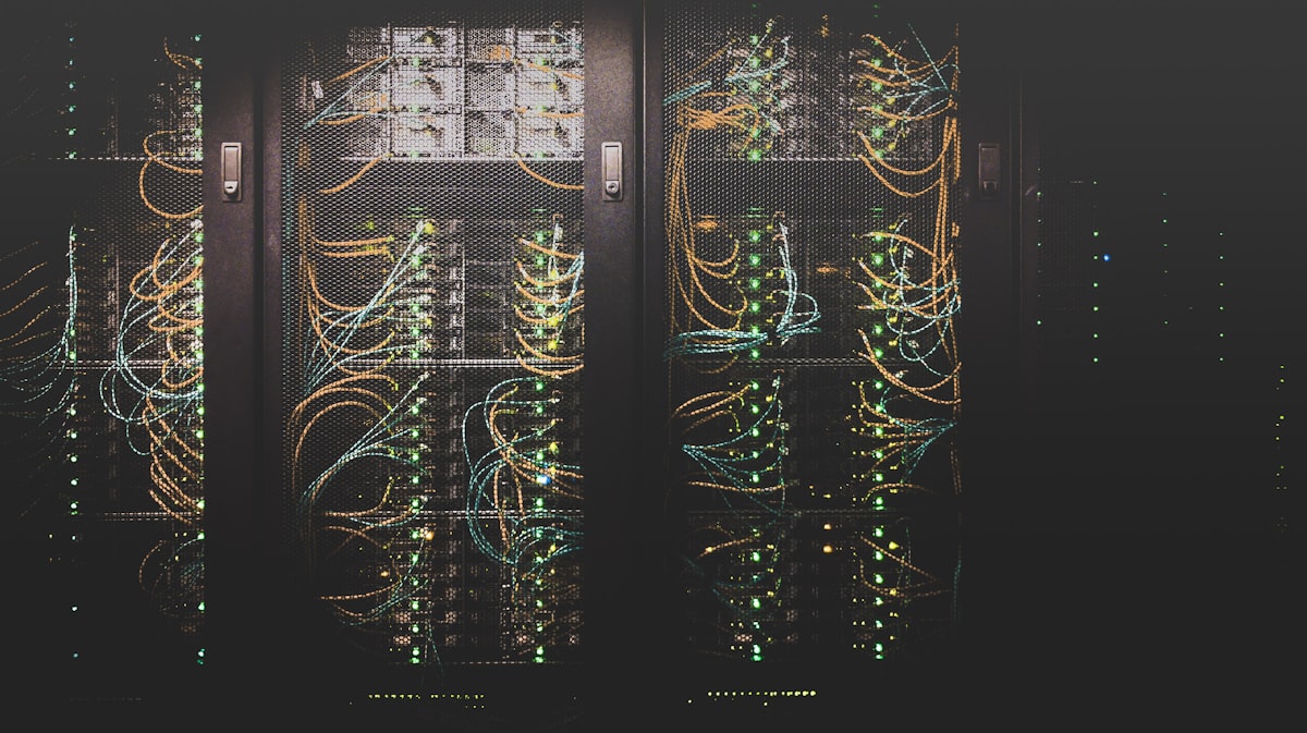
Server Rack
Contains servers and network equipment that provide shared services and resources.

Network Printer
A printer that can be connected to a network and used by authorized users.
| Device | Detailed Explanation | Example Use |
|---|---|---|
| Router | Connects different networks and forwards traffic toward another network or destination. | Connecting a school LAN to an internet service. |
| Switch | Connects devices within a local network and forwards local network traffic. | Connecting computers in a laboratory. |
| Access Point | Provides a wireless connection point for suitable devices. | Allowing laptops and phones to join Wi-Fi. |
| NIC | A network interface that allows a device to connect to a network. | Ethernet or wireless interface in a computer. |
| Firewall | Controls traffic according to configured security rules. | Restricting unwanted traffic. |

How Network Devices Can Work Together
INTERNET → [MODEM] → [ROUTER] → [SWITCH] → PCs / PRINTER / SERVER
                                   |
                              [ACCESS POINT]
                                /       \
                            PHONE      LAPTOP
5. Transmission Media
Transmission media is the path through which communication signals travel. Media can be guided, meaning signals travel through a physical medium, or unguided, meaning communication uses wireless signals.
Twisted Pair Cable
Commonly used for Ethernet connections inside buildings. It is practical for many local area networks.
Fiber Optic
Uses light to transmit information and is useful where high capacity and longer distances are required.
Coaxial Cable
Uses a central conductor surrounded by insulation and shielding.
Wireless
Uses electromagnetic signals and allows supported devices to move without a physical data cable.
Pictures of Transmission Media and Networking Tools
These are enlarged real visual examples. Compare the physical appearance of the cables and wireless equipment so that you can identify them during practical work.

Ethernet / Twisted Pair Cable
A common LAN cable used to connect computers, switches, routers and other Ethernet devices.

Fiber Optic Cable
Carries information using light and is useful for high-speed and longer-distance communication.

Coaxial Cable
A cable with a central conductor surrounded by insulating and shielding layers.

Wireless Networking
Uses radio signals to connect devices without a physical data cable.
Step-by-Step: Choosing a Suitable Medium
6. Network Protocols
A network protocol is a set of agreed rules used by devices when communicating. Protocols help devices understand how information should be organized, sent, received and processed.
| Protocol | Purpose | Simple Example |
|---|---|---|
| IP | Supports logical addressing and communication between networks. | Identifying a network destination. |
| TCP | Provides reliable, ordered communication for appropriate applications. | Reliable application data transfer. |
| UDP | Provides connectionless transport with lower overhead for suitable uses. | Time-sensitive applications. |
| HTTP/HTTPS | Used for web communication; HTTPS provides protected communication. | Opening a website. |
| DNS | Helps translate names into network addressing information. | Using a website name. |
| DHCP | Can automatically provide network configuration information to clients. | A new computer joining a managed network. |
7. IP Addressing
An IP address is a logical address used to identify a device interface on an IP network and help direct information toward the correct destination.
IPv4 Structure
  192        .       168        .        1         .       10
   |                    |                  |                  |
 Octet 1              Octet 2            Octet 3            Octet 4
Step-by-Step: Basic Network Configuration
- Open the device's network settings.
- Select the correct network interface.
- Choose automatic configuration or manual configuration as required.
- Enter the required address information when manual configuration is used.
- Save the settings.
- Test communication with an appropriate destination.
- If the test fails, review the configuration systematically.
8. OSI Model
The OSI model is a seven-layer conceptual framework used to describe how communication functions can be organized. It is useful for learning and troubleshooting because a problem can be investigated layer by layer.
The Seven OSI Layers
+-----------------------------+
| 7. APPLICATION              |
+-----------------------------+
| 6. PRESENTATION             |
+-----------------------------+
| 5. SESSION                  |
+-----------------------------+
| 4. TRANSPORT                |
+-----------------------------+
| 3. NETWORK                  |
+-----------------------------+
| 2. DATA LINK                |
+-----------------------------+
| 1. PHYSICAL                 |
+-----------------------------+
9. Network Security
Network security involves protecting devices, services, communication and information from unauthorized access, misuse, damage and disruption. Effective security usually combines technology, procedures and responsible user behavior.
Strong Authentication
Use appropriate authentication and avoid easily guessed passwords.
Access Control
Give users only the access they require for legitimate work.
Updates
Keep supported systems and applications updated according to an appropriate maintenance process.
Backups
Maintain appropriate backups of important information and test recovery procedures.
Security Procedure
- Identify important systems and information.
- Identify likely risks and weaknesses.
- Apply appropriate technical and administrative controls.
- Educate users about suspicious activity.
- Monitor and review security controls.
- Respond appropriately to security incidents.
10. Network Troubleshooting
Network troubleshooting is a systematic method of finding the cause of a communication problem, correcting it and confirming that the network works correctly afterward. Working step by step prevents random changes and makes it easier to identify the actual cause.
Detailed Procedure
- Ask what exactly is failing and when the problem started.
- Determine whether one device or many devices are affected.
- Check power, cables, connectors and status indicators.
- Check network configuration.
- Test communication in logical stages.
- Locate the point where communication stops.
- Apply the most appropriate correction.
- Test again to confirm that the issue is resolved.
- Document the cause and solution.
11. Practical Activities
Activity 1: Build a Small Local Area Network
- Identify the computers and networking devices required.
- Choose an appropriate topology.
- Connect end devices to the central networking device.
- Check all physical connections.
- Configure suitable network settings.
- Test communication between devices.
- Draw and label the final network arrangement.
Activity 2: Identify Network Devices
Examine available networking equipment. Identify each device, describe its purpose and explain where it would be placed in a network.
Activity 3: Troubleshoot a Controlled Problem
Create a simple fault such as an incorrect network setting or disconnected cable. Use the troubleshooting procedure above, record your observations and verify the final solution.
📝 Computer Networking Exam
Each new exam selects and shuffles questions from the question bank.